Simplifying your future
Solving DC/DC Power Challenges in Military Avionics Through Modularity (Part 2)
After outlining the key standards for military and avionics power supply design in part 1, this part 2 turns to one of their most demanding challenges: managing input bus electrical overstress.
The wide bus voltage range, transients, spikes, and undervoltage conditions all present a strict set of constraints for the power electronics designer. This part 2 of the story breaks down, how overvoltages are characterized in these standards and provides engineers with practical methods to suppress them. It looks at spikes and surges and explains, how a transient limiter works.
By Christian Jonglas, Technical Support Manager, GAIA Converter.
When it comes to spikes and surges, it always comes back to two basic characteristics: duration and energy. What is the difference between these two and what does these mean for the design engineer?
Spikes
What is referred to as “spike” in this article is an over-voltage that lasts less than 1 ms. When the duration exceeds this value, it is common to refer to the event as a “surge.” Understanding this distinction is crucial because each kind of over-voltage requires treatment by a different device. Typically, spike protection is expected to implement a clamping device such as a Transient Voltage Suppression (TVS) diode, a Metal Oxide Varistor (MOV), or a gas discharge
tube. This is possible because the relatively short duration of spikes means they contain an amount of energy that can be handled by a single clamping component. To select any clamping device’s protection, three parameters must be considered that will be provided by the standard: the peak voltage, the duration, and the energy or the
source impedance.
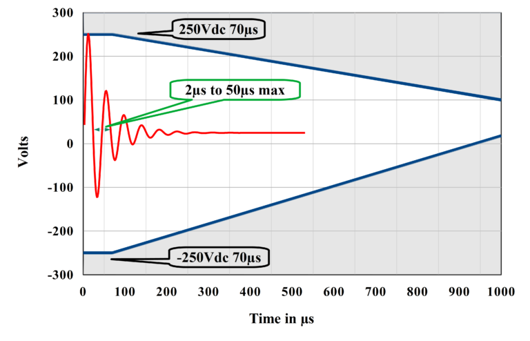
Let’s take as example the injected voltage spikes described into the MIL-STD-1275F. The table 3 in part 1 of this story shows a spike with the following specifications: +/-250 V 70 μs and 200 mJ. This is referring to the envelope of the transient spike described into the standard (Figure 1 below). Over the course of the last three revisions of Mil-STD-1275, the maximum energy specified increased from 15 mJ in revisions C and D to 2000 mJ in revision E, and finally returned to 200 mJ in revision F.
We have the peak voltage, the pulse duration, and the energy—but to properly match the clamping protection to our design, one more parameters is needed: the minimum clamping voltage, which is the voltage threshold at which the device begins to conduct significant current. According to the MIL-STD-1275F standard, the most severe threat to the clamping device itself is a 100 V surge with a 50 ms duration. To prevent damage from excessive current flow during this extended event, the protection device must begin clamping at or slightly below 100 V. We can now select a clamping device rated to trigger at 100 V and capable of withstanding 200 mJ of energy.
An equivalent graph for DEF-STAN 61-5 is shown in Figure 2 with a normal operating range for 12V nominal of 9-19V, or 18-36V for 12V systems. Note that this is shown as 19-36V elsewhere in the standard, confusingly. The standard specifies the maximum and minimum voltages for 5 minutes, but practically, any connected equipment must withstand this continuously.