Simplifying your future
Solving DC/DC Power Challenges in Military Avionics Through Modularity (Part 4)
While the first three episodes detailed military and avionic standards and front-end solutions, this last part 4 delves into the core of energy conversion. Part 4 will examine the critical challenge of selecting the optimal DC/DC converter topology and mode of operation, tackle magnetic circuit design, and address auxiliary functions and reliability concerns. Finally, this story will outline a comprehensive modular power architecture, built from the functions previously discussed and realized through specific COTS modules. PCB layout considerations will also be discussed.
By Christian Jonglas, Technical Support Manager, GAIA Converter
Designing a full DC/DC converter with discrete components is definitively the most complex, time-consuming, and risky approach.
Consequently, engineers who choose this path probably have compelling reasons. Sometimes the required specifications aren’t available in Commercial Off-The-Shelf (COTS) products. Other times, the form factor of a COTS DC/DC converter – despite offering better power density – doesn’t fit the customer’s needs, or the designer requires a unique function unavailable in COTS solutions. For engineers opting for a discrete design believing it will outperform a COTS-based solution or hoping to master component procurement, it is paramount to carefully balance the risks and benefits.
The multi-phase design process itself presents significant challenges in terms of topology choice, magnetics & switching component selection as well as control loop and protection.
Topology Choice
The choice of topology is a critical decision which requires a highly skilled power supply designer. For example, selecting a flyback topology for low-power isolated DC/DC converter leverages its low component count, which improves reliability through higher MTBF figures. To simplify design, engineers may choose Continuous Conduction
Mode (CCM) operation. However, CCM demands a larger transformer with a correctly rated air gap to prevent core saturation, and an accurate output voltage control for limiting the light loads voltage raise. Conversely, Discontinuous
Conduction Mode
(DCM) yields a smaller transformer size and more stable light-load voltage regulation—at the expense of higher ripple current that increase components stress lowering the MTBF.
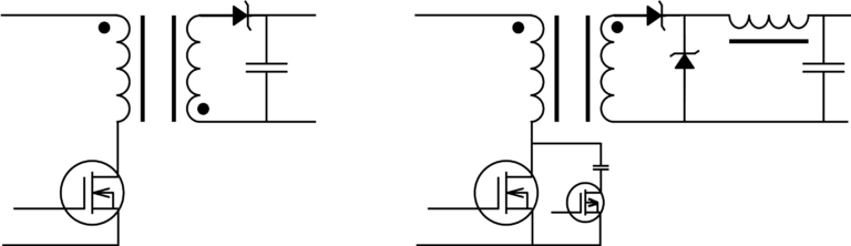
Figure 1: The flyback topology, with its low component count and a single magnetic circuit that provides both isolation and energy storage, is ideal for achieving high MTBF. The forward topology using a transformer for isolation and a separate power inductor for energy storage is essential for high powers.