Simplifying your future
Solving DC/DC Power Challenges in Military Avionics Through Modularity (Part 3)
Following our exploration of military standards and practical transient suppression, we now turn to a common challenge in switch-mode power supply (SMPS) design: containing conducted noise. In this article we will explore conducted noise paths and filtering techniques. Traditionally, managing bus interruptions has relied on large bulk capacitors to maintain energy on the primary side. In this third part of the series, we examine how GAIA-converter’s approach—embedding a boost converter within a board-mounted module—reduces the required capacitor value for a given hold-up time.
By Christian Jonglas, Technical Support Manager, GAIA Converter
DC/DC converters, as switch-mode power supplies, generate conducted noise on their input and output leads. This noise appears as an alternating current waveform superimposed on the DC current, comprising multiple frequency harmonics. These harmonics originate from switching components (e.g., MOSFETs and rectifying
diodes) that, when combined with parasitic capacitance or inductance, form high-frequency resonant circuits during transient operation.
Two distinct propagation modes exist, each requiring specific mitigation techniques for DM noise and CM noise: Differential Mode (DM) Noise: Current flows between the positive lead and its return path (negative lead). This noise is relatively straightforward to suppress, typically requiring only a basic LC filter with ~40 dB/decade attenuation to meet compliance limits.
Common Mode (CM) Noise is more challenging to eliminate, CM noise flows simultaneously through both positive and negative leads, returning via earth ground. It propagates through parasitic capacitances (e.g., across isolation barriers or chassis connections), inducing AC voltages along its path. CM noise arises from high dV/dt switching transitions and typically occupies higher frequencies.
For DO-160 and MIL-STD-461, Limits are specified in dBμA, where:
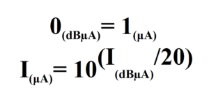
Figure 1: To convert a current in dBμA to its value in μA the reverse logarithmic needs to be used.